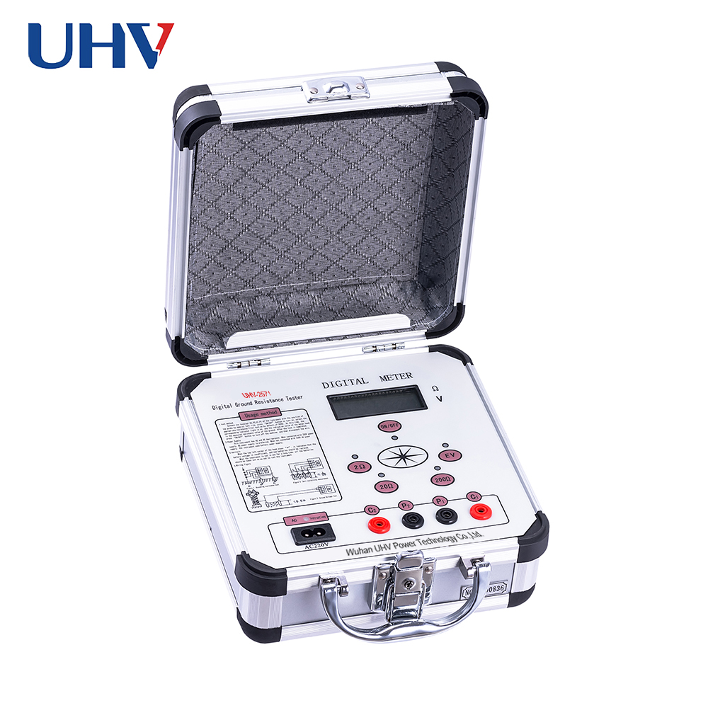
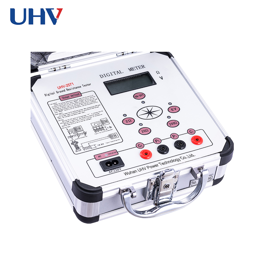
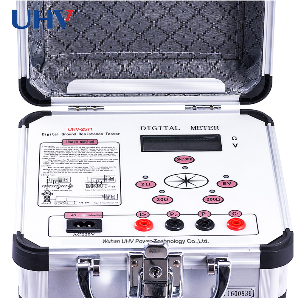
Ground Resistance Tester is a device used to measure and test electrical grounding systems. Grounding allows for optimal electrical continuity between the conductive object and the earth. Effectively grounded equipment is permanently connected to ground by a ground connection that has a sufficiently low impedance and sufficient current-carrying capacity that does not result in dangerous voltage accumulation due to a ground fault current.

Types of Earth Resistance Testers
Earth resistance testers can be used to make several different measurements, including:
Grounding system resistance
Resistencia de aislamiento
Planetary continuity
Corriente de fuga
Ground key
Grounding system resistance and insulation resistance are common measurements made using a grounding resistance tester. Grounding System Resistance Testers are used to measure grounding systems in construction projects and roads, telecommunications projects, and other applications. An insulation resistance tester measures the resistance of an insulator or insulator.

Fields of application
Ground resistance testers can be used to measure ground continuity, leakage current, and ground connections. Grounding continuity equipment is used to test electronic instruments and appliances. A leakage current tester measures the amount of current leaking to the ground. These devices are important for maintaining the safety of instruments that meet people. Ground connection ground resistance tester is used for ground connection or high current continuity testing. These tests are performed to confirm the electrical integrity of the instrument. Other types of ground resistance testers are also available.

especificación
Most earth resistance testers have an analog or digital display, or an LED indicator. An analog gauge displays a numerical value on the dial, usually with a hand that moves when a signal is applied. The digital meter provides digital readings. Light-emitting diodes (LEDs) and liquid crystal displays (LCDs) are common types of digital displays. LED indicators use light to indicate that the test is in progress. In some models, the LED light flashes throughout the test.
The Earth Resistance Tester is available with several different interfaces. Options include GPIB, RS232, printer port, scanner port, and printout. The General Interface Bus (GPIB) is designed to connect computers, peripherals, and lab equipment. The RS232 interface of the ground resistance tester is used for serial communication between the instrument and the computer. Printer port devices have connectors or ports designed to connect with printers. The scanner port is like the printer port but is designed to interface with the scanner. Another common interface for ground resistance testers is printout. A printout is a hard copy of formatted data collected during testing. Other interface types for ground resistance testers are also available.


