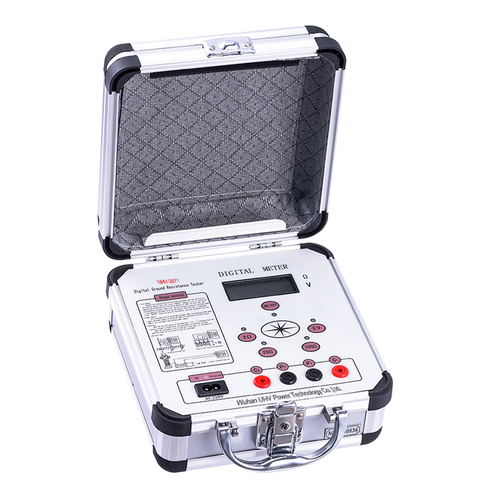
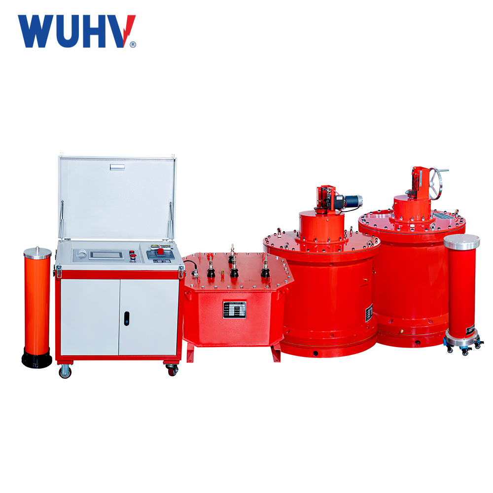
The grounding resistance tester La energía UHV puede ayudar a muchos trabajadores de energía a realizar varias pruebas de energía de manera más conveniente.

Soil resistivity is an indicator that measures the degree of resistance of soil to electrical current. The soil resistivity test is currently determining this measure. Therefore, it is a key factor in designing systems that rely on the current passing through the Earth's surface. Understanding soil resistivity and how it varies with soil depth is essential for designing electrical grounding systems. In substations, or used for lightning rods. This measurement is also required for the grounding electrode design of substations and high-voltage direct current transmission systems. Because most substations use the earth to conduct all or most of the fault current when a grounding fault occurs in the system.
What is soil resistivity testing
Single line return line
In a single line power transmission system. The Earth itself serves as a pathway for conduction from end customers (consumers) back to transmission devices. Usually, the impedance of a grounding connection should not exceed a certain value. In addition, it is not allowed to exceed a certain maximum step voltage to avoid endangering people and livestock.
Due to moisture, temperature, and chemical composition, soil resistivity values can undergo significant changes. Typical values are:
Typical values: from 10 to 1000 (Ω. m)
Outliers: from 1 to 10000 (Ω. m)
The unit of resistivity for Si is Ohm meter (Ω. m);
You will find a wide range of typical soil resistivity values in the Military Manual 419 (MIL-HDBK-419A). This includes reference tables and formulas for the resistance of various rods and wires buried in soil with known resistivity. And because it is copyright free, these numbers are widely copied and sometimes not recognized.
Explain soil resistivity testing
Soil resistivity testing is the process of measuring soil volume to determine soil conductivity. The resulting soil resistivity is usually expressed in ohms meters.
This type of grounding resistance test is the most critical factor in the design of electrical grounding systems. This is indeed the case when discussing simple electrical designs and specialized low resistance grounding systems. Or more complex issues involved in the study of Earth's potential rise (EPR). Therefore, a good soil model forms the foundation of all grounding designs. In addition, it has evolved from precise soil resistivity testing.
Obtain a 'good' soil model that accurately represents the geology. It's easier said than done! Because there may be many sources of errors that can infiltrate and capture people who are not yet introduced or trained. Therefore, it leads to unsafe designs.


