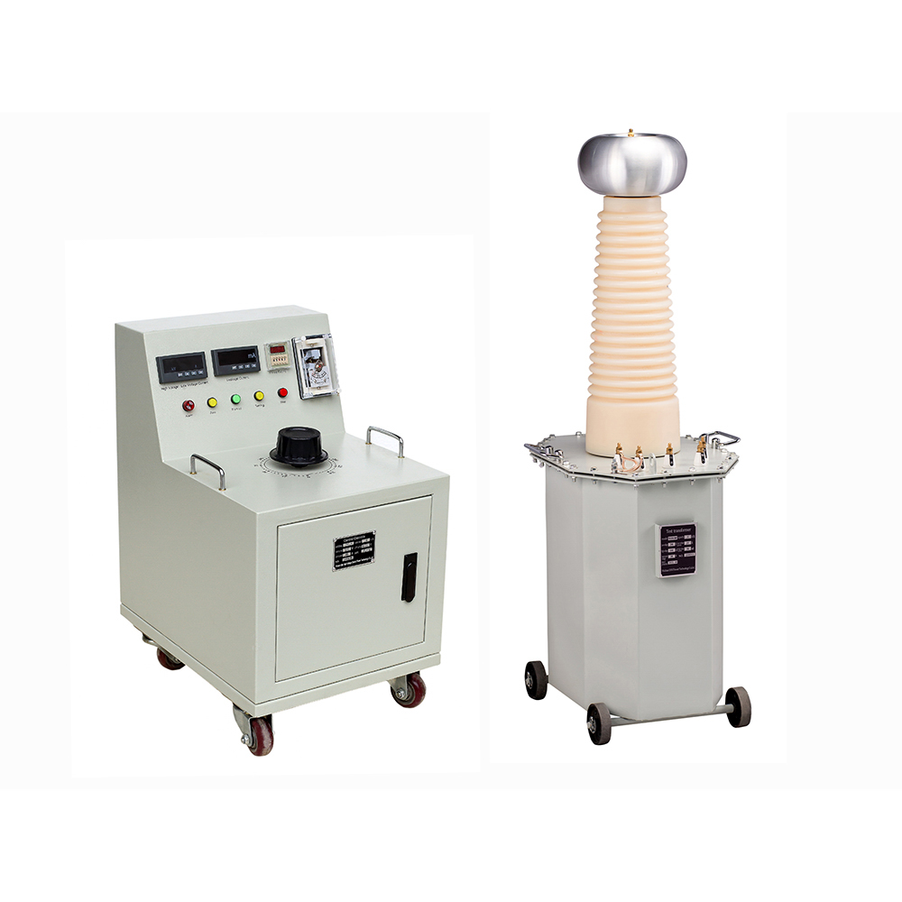
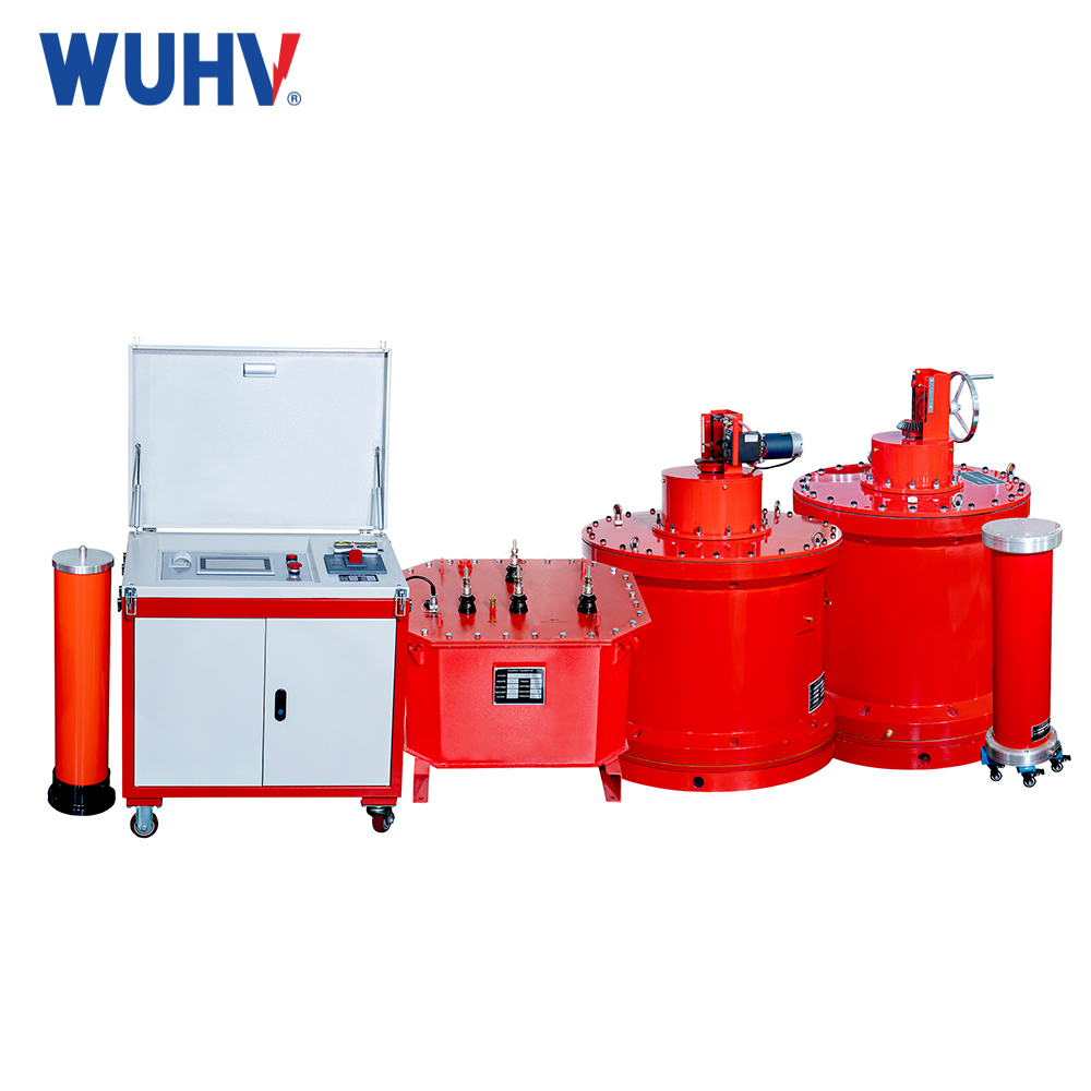
The professional production of high-voltage test transformers in UHV power can help many power workers conduct various power tests more conveniently.

A test transformer is a transformer used for conducting power frequency withstand voltage tests on various electrical products and insulation materials, also known as a high-voltage test transformer. The main features of this system are as follows:
A. High voltage. The rated voltage of a single machine is 50, 100, 150, 250, 500, and 750 kV.
B. High voltage waveform requirements. Usually, power is supplied by a generator set, filters are used, and the magnetic density of the transformer itself should not be high.
C. Short working hours. Due to the short withstand time of the tested product (1 minute or 5 minutes), the working time is generally within half an hour.
D. The current is small. The rated current of the experimental transformer is actually the capacitance current of the measured object, so it is usually less than 1a.
There are four types of test transformers: single tube type, insulated tube type, double tube type, and series type.
Double tube type is usually used for cascading, and when used alone, it is double tube type.
Series connection is formed by connecting the high voltage windings of two or more double tube test transformers in series. The winding of this product consists of balanced winding, high voltage winding, and low voltage winding in the inner and outer directions of the left iron core column, while the right iron core consists of balanced winding, high voltage winding, and cascaded excitation winding (the last one is not). The iron core and oil tank are connected by two high-voltage winding wires, which are also 1/2 high voltage. The low-voltage winding of the latter is powered by the cascaded excitation winding of the former, causing the potential of the latter to rise.
The test transformers used in cable and large motor tests, external insulation pollution tests, and line corona tests have high current (4-10a) and long service life. Therefore, by using a series resonant test transformer, the actual capacity of the transformer can be reduced, and the feeding (input) power can be lowered to 1/7-1/10 of the output power. It synchronously adjusts the inductance of the adjustable reactor based on the capacitance value of the tested object, thereby changing the inductance value of the tested transformer to match the capacitance of the tested object and achieve power frequency resonance The total voltage of the test transformer during resonance is the test voltage of the test object. The voltage of the feeding transformer is regulated by a dynamic voltage regulating transformer. Its power consumption and the power drawn from the grid depend on the quality factor of the resonant circuit, and therefore are much smaller than the resonant capacity.
The single casing is of the single high voltage casing type. The high-voltage A end of the high-voltage secondary winding is led out from the high-voltage bushing, and the X end is grounded or led out from the low-voltage bushing, completely insulated from the ground. When there is a series excitation winding, the A end of the high-voltage winding and its A1 end are led out from the same high-voltage bushing. The axe of the low-voltage winding is at the innermost part, and sometimes there is a measuring winding between the high and low voltage windings. There is a grounding plate installed outside the measuring winding to ensure the safety of personnel and instruments. The core is a single-phase single column side twisted type.
The insulation cylinder uses a simple insulation method (phenolic cold paper or epoxy glass cloth tube) instead of the oil tank and high-pressure sleeve. The iron core is a single-phase double column structure with half of the high voltage, requiring an insulated support plate to be insulated from the ground and placed horizontally. The high voltage terminal a of the high voltage winding is connected to the metal upper pelvis, and the grounding terminal X and the a and X ends of the low voltage winding are led out from the base. This structure has a small volume and light weight, and is commonly used in products with a voltage of 250kV and below.


