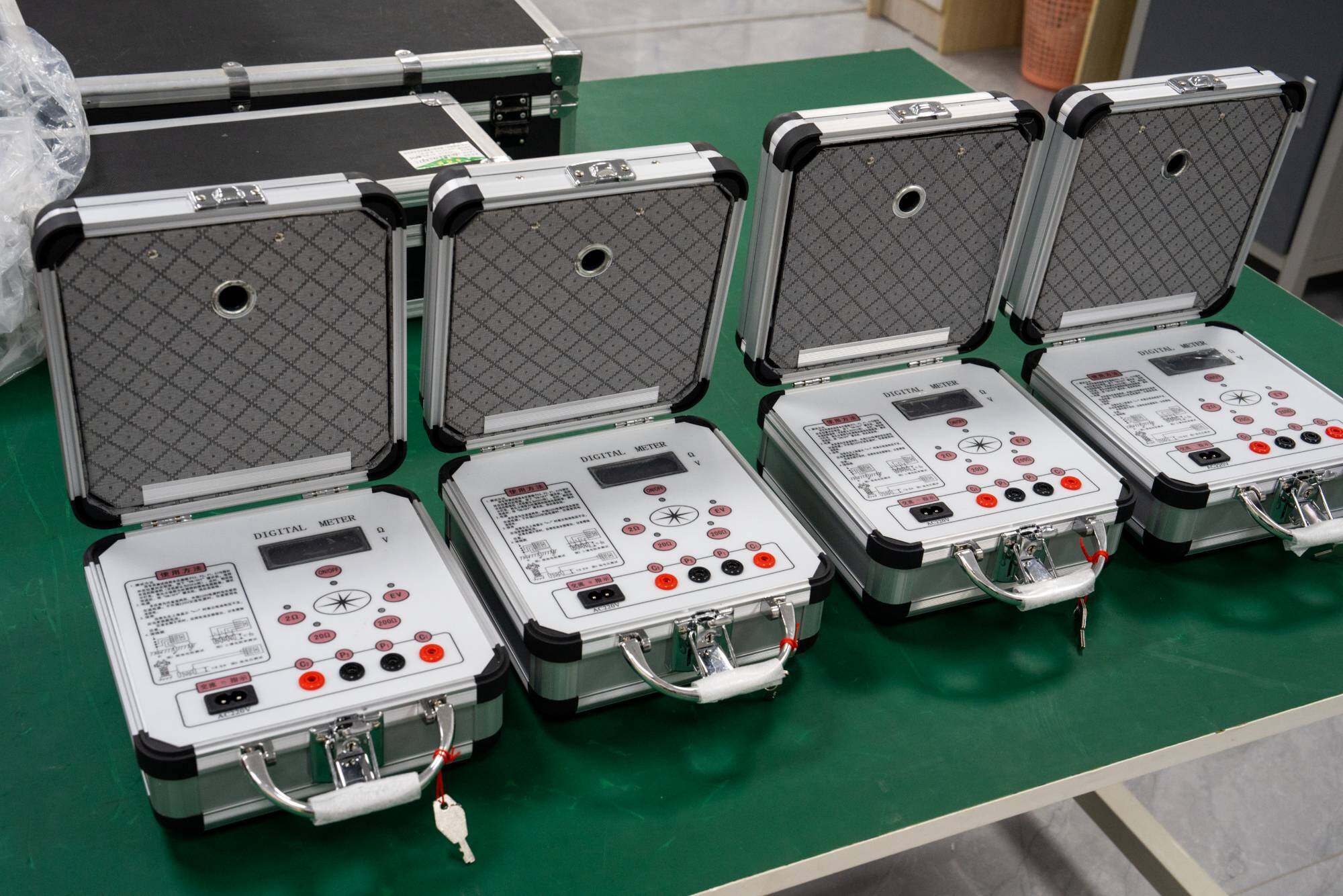
The grounding resistance testerLa energía UHV puede ayudar a muchos trabajadores de energía a realizar varias pruebas de energía de manera más conveniente.
In electrical lightning protection testing, many factors can lead to inaccurate readings of grounding resistance. In summary, there are generally several reasons.
1. When inspecting high-rise buildings, using excessively long or thick wires can increase line resistance and induced voltage, resulting in measurement errors. At this time, wires with relatively low resistance should be used to minimize measurement errors as much as possible.
2. The insertion depth of the iron drill should be greater than 1/4 of the length of the iron drill. Otherwise, testing errors may occur. So. During testing, the iron should be deepened as much as possible.
3. In the case where the tested grounding electrode is "common ground", due to poor insulation or short circuit of the equipment, the grounding device generates a certain grounding voltage to the ground, making the reading unstable. At this time, the power should be cut off for testing, or the place where the card is disconnected should be cut off to avoid the impact of ground voltage on the test.
4. Poor contact. When the tested object rusts or the detection line breaks, intermittent connections or high resistance may be found during detection. At this point, rust should be removed first. If it still cannot be ruled out, use a multimeter to check the conductivity of the detection line.
5. Due to the fact that the grounding resistance tester measures the grounding resistance of the grounding body by emitting and receiving current from the iron rod, mutual interference may occur when the distance between two iron rods or between two rods and the grounding body is too close. And the errors that arise from it. So when measuring. The grounding electrode, voltage electrode, and current electrode are arranged in sequence. These three points are on a straight line, 20 meters apart from each other.
6. When there are substances such as soil or sand at the tested location, measurement errors may occur due to the different electrical resistivity of the upper and lower layers of soil. At this time, deep iron should be drilled to ensure full contact with the soil under the cushion layer or to avoid the cushion layer, in order to reduce measurement errors.
7. When buried metal objects such as grounding devices and metal pipelines are complex, they may change the direction of the current at each pole of the measuring instrument, causing poor or unstable measurements. At this point, it is necessary to first understand the layout of the grounding body and metal pipeline, and choose a location with relatively less impact for measurement.
8. Inaccurate measurements are caused by surface potential differences or strong magnetic fields. At this time, one should stay away from places with large potential differences or strong magnetic fields. If unavoidable, the detection line should be relatively short to reduce measurement errors.
9. Measurement errors are also caused by factors such as the operator not following the instructions during use, failure to repair the instrument in a timely manner when it malfunctions, inaccurate instrument readings, or prolonged lack of recognition.


