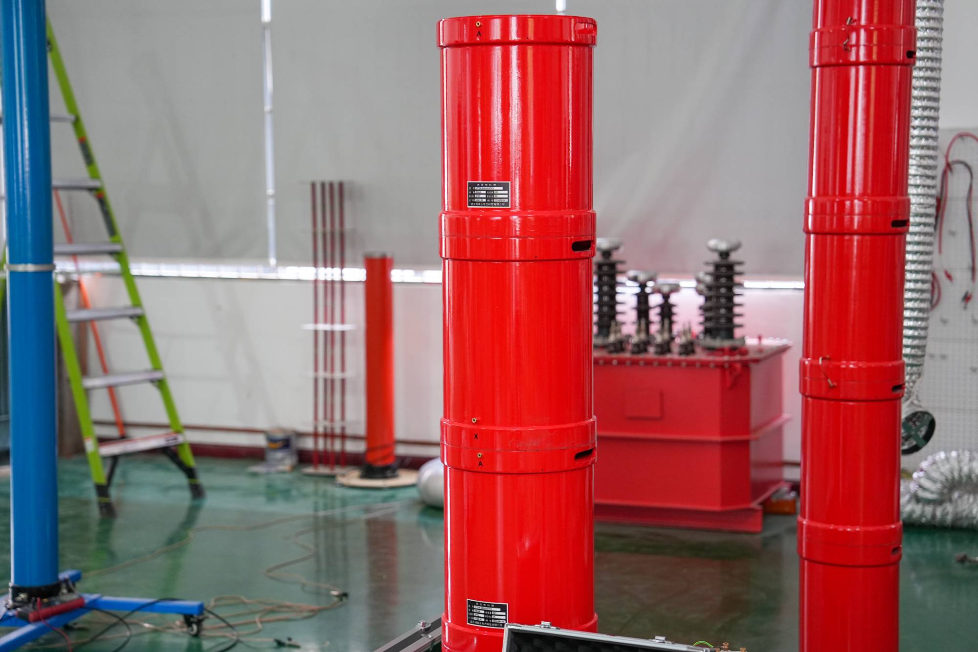
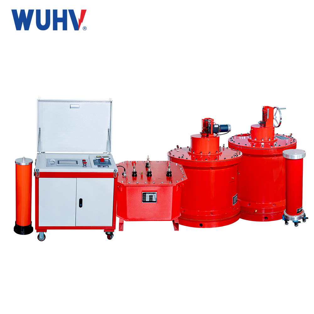
A Variable-Frequency AC Series Resonant Test System is an insulation performance testing device that utilizes the principle of series resonance and variable-frequency technology to achieve efficient high-voltage output. It is specifically designed for on-site AC withstand voltage testing of large electrical equipment (such as power cables, transformers, GIS, etc.). Its core principle is to adjust the power supply frequency to achieve resonance in the circuit, thereby generating the required high voltage using a relatively small-capacity power supply.
I. System Components
1.Variable-Frequency Power Supply
The core control unit, outputs a sine wave with adjustable frequency (typically 30-300 Hz).
Automatically scans for the resonant point and adjusts the frequency in real-time to maintain resonance.
2.Excitation Transformer
Provides voltage step-up and isolation, boosting the output voltage of the variable-frequency power supply to the initial voltage required for resonance (designed with small capacity).
3.Resonant Reactor(s)
Key component(s), with adjustable inductance (achieved via multiple units in series/parallel). Forms a series resonant circuit with the test object capacitance Cₓ.
4.Capacitive Voltage Divider
Measures the voltage across the test object (U_{Cₓ}) and provides a feedback signal for voltage stabilization and protection.
5.Compensation Capacitor (Optional)
Used when the test object capacitance is too small (e.g., short cable sections). Connected in parallel to lower the resonant frequency.
6.Control & Protection System
Integrates overvoltage, overcurrent, and flashover protection, along with automatic tuning and data logging functions.
II. Working Principle
1.Establishing Resonance Condition
Adjust the output frequency f of the variable-frequency power supply so that the reactor inductive reactance X_L = 2πfL equals the test object capacitive reactance X_C = 1/(2πfCₓ). This creates series resonance.
2.High Voltage Generation
At resonance, the circuit impedance is minimal (purely resistive) and the current is maximum. The voltage across the reactor and the test object rises to Q times the input excitation voltage (Q is the circuit quality factor, typically 20-80):
U_{Cₓ} = Q × U_{input}
Example: Input voltage 500V, Q=50 → Test object voltage reaches 25kV.
3.Voltage Stabilization Control
The capacitive divider monitors U_{Cₓ} in real-time. This signal is fed back to the variable-frequency power supply for closed-loop control, maintaining the set voltage.
III. Core Advantages
1.High Efficiency & Portability
Power supply capacity only needs to compensate for circuit losses (1/10~1/20 of traditional methods), reducing equipment weight by over 70%. Ideal for on-site transportation and setup.
2.Safety & Reliability
If the test object breaks down, the resonance condition collapses, causing the high voltage to disappear automatically. Short-circuit current is limited.
3.Pure Output Waveform
Outputs a pure sine wave, meeting power frequency equivalence requirements (e.g., IEC 60840 standard).
4.Precise Control
Fully automatic frequency and voltage tuning, with voltage accuracy reaching ±1%.


