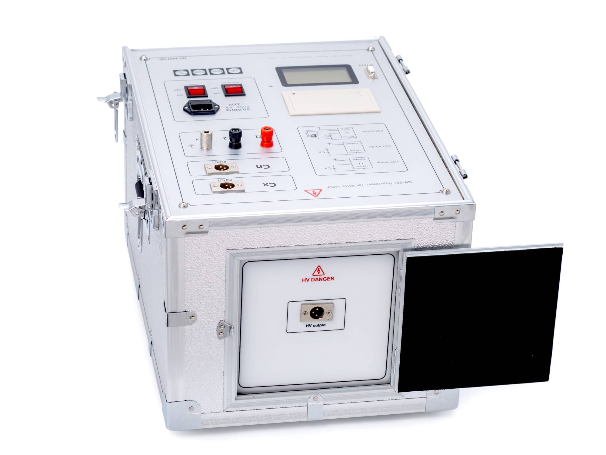
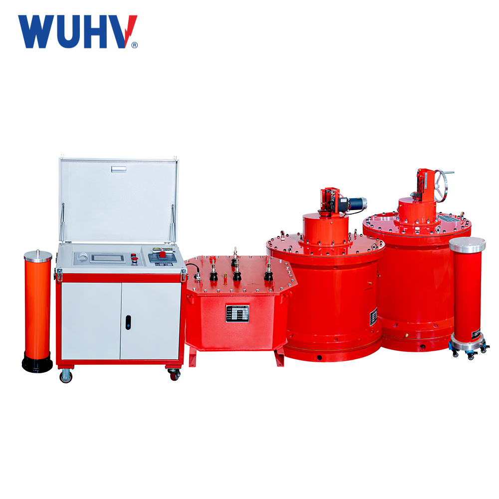
The core instrument used for dielectric loss testing (loss tangent tanδ measurement) is a Dielectric Loss Test Set, also known as a Tan Delta Tester or Schering Bridge. Based on technical principles and automation levels, the main types are:
1. Traditional Schering Bridge
Principle: Classic balanced bridge method requiring manual adjustment of resistive/capacitive arms to achieve balance for calculating tanδ and capacitance.
Characteristics:
High accuracy (historically the laboratory standard).
Complex operation, demanding skilled personnel.
Slow testing speed.
Requires external HV source (e.g., test transformer) and reference capacitor.
Application: Laboratory precision measurements or calibration reference. Rarely used for field preventative testing today.
2. Digital Automatic Dielectric Loss Testers
Principle: Uses digital measurement techniques (e.g., digital sampling, vector analysis) to automatically measure current magnitude/phase difference under applied voltage. Directly calculates and displays tanδ, capacitance (Cx), power factor (PF), leakage current, etc. Typically integrates HV source and measurement unit.
Characteristics:
Industry Standard: The dominant choice for field and factory testing.
Automated: Simple operation (one-button testing), automatic calculation/display, no manual balancing.
Fast & Efficient: High testing speed.
Integrated: Usually contains built-in HV source (outputting AC test voltages like 10kV or higher) and reference measurement unit. Portable (though larger capacity units may be heavier).
Versatile: Tests various equipment (transformer windings-windings/ground, bushings, CTs/VTs, cables, capacitors). Supports multiple test modes (Direct/Standard, Reverse, GST/GST-Guard).
Strong Anti-Interference: Features digital filtering and noise suppression.
Data Management: Stores results; some models offer Bluetooth/USB transfer or printing.
Test Modes:
Direct/Standard Mode: HV applied to test object's HV terminal (e.g., transformer HV winding), measurement terminal connected to LV terminal (or ground screen). For objects with one end grounded (e.g., transformer windings).
Reverse Mode: HV applied to HV terminal, measurement terminal floated; instrument chassis (ground) connected to test object's LV terminal. For objects with neither end grounded (e.g., capacitive bushing tap).
GST/Guard Mode: Uses the test object itself as a voltage source (primarily for CVT measurements).
3. Variable Frequency Dielectric Loss Testers (VFDS / VLF)
Principle: Extends digital automatic testers with variable frequency capability (typically adjustable between 15Hz - 400Hz+).
Characteristics & Advantages:
Key Advantage: Superior Anti-Interference: Field environments often have strong 50/60Hz power frequency noise. VFDS shifts test frequency away from interference (mains frequency & harmonics), drastically improving signal-to-noise ratio for more accurate/reliable tanδ results, especially in noisy substations.
Retains all benefits of digital automatic testers (automation, integration, versatility).
Application: Essential for precise measurements in high-interference field environments (e.g., live substations, testing near energized equipment). The preferred high-end choice for modern field testing.


