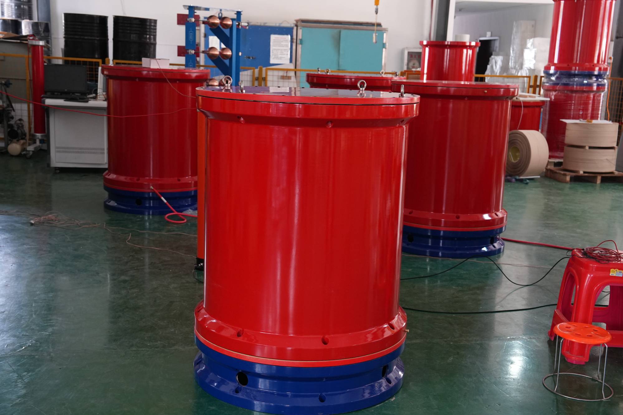
Wuhan UHV specializes in producing series resonance (also known as power frequency withstand voltage test equipment). Next, we will share with you the protective measures for the grounding arrangement of power frequency withstand voltage test equipment.
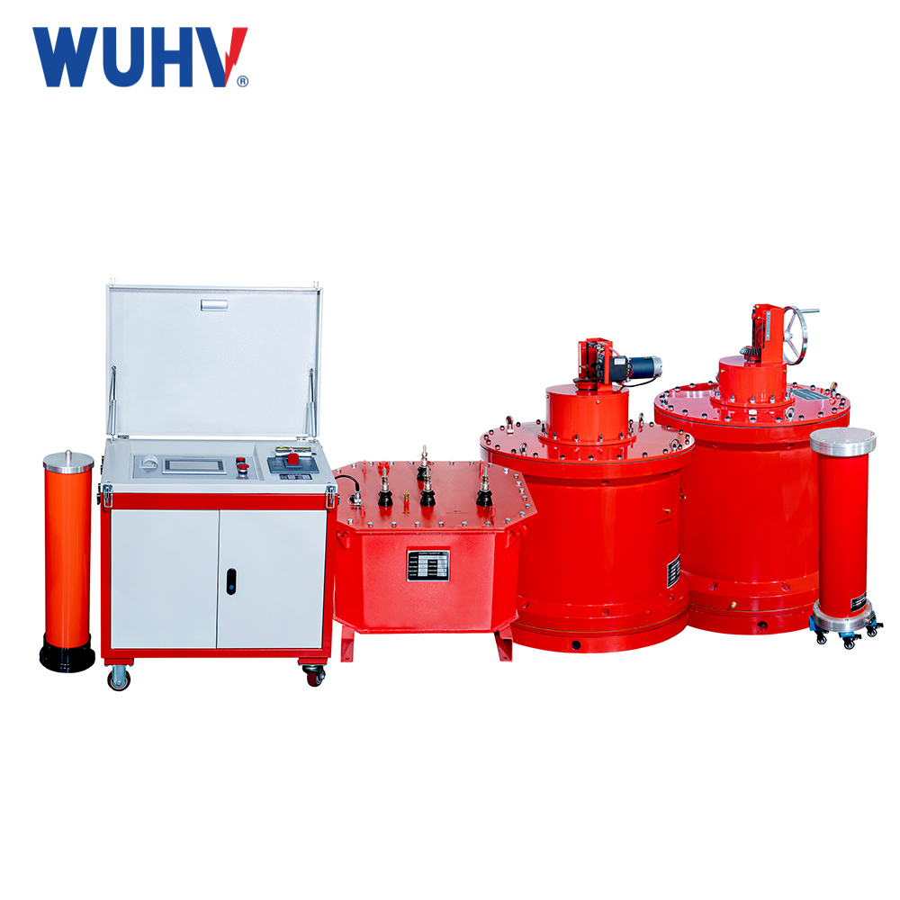
Variable frequency series resonance is mainly composed of variable frequency controller, excitation transformer, high-voltage reactor, high-voltage voltage divider, etc. During the frequency conversion series resonance test, the capacity of the excitation transformer should be greater than the active power P, and the transformation ratio of the excitation transformer should be reduced as much as possible on the premise that the minimum output voltage of the excitation transformer meets the test requirements, so as to correspondingly reduce the input current on the primary side of the excitation transformer. Due to the large capacitance of the tested cable, if the test sample breaks down or high-voltage leads discharge to ground during the test, transient overvoltage may occur at the grounding end of the cable, the test grounding wire, and the control box casing. This equipment has been equipped with multiple transient overvoltage protection measures in the control box and main components to ensure its normal operation. In addition, the following protective measures should be taken in the layout of the test grounding wire:
1. The test equipment (resonant reactor, voltage divider, excitation transformer, etc.) should be placed as close as possible to the tested cable head to reduce the length of the test grounding wire, that is, to reduce the inductance of the grounding wire.
2. Adopt a specially designed one point grounding test grounding wire group. Special attention should be paid to keeping the test grounding wire as short as possible and not arbitrarily extending the length of the grounding wire.
3. During the experiment, the operator should not touch the metal casing of the control box except for the tuning and voltage regulating insulation knobs, otherwise there may be a slight stinging sensation when piercing or discharging on the high-voltage side. When conditions permit, it is recommended that operators work standing on rubber insulation pads.
4. The test transformer has three terminals: 800V, 1000V, and 1500V. When the required high voltage of the system is less than 15kV, the 800V terminal is selected. When the required high voltage of the system is greater than 15kV and less than 60kV, the 1000V terminal is selected. When the required high voltage of the system is greater than 60kV, the 1500V terminal is selected.
Transformer, GIS system, SF6 switch CT/PT、 Insulators, busbars, cables, sleeves and other capacitive equipment are the most common electrical devices in substations. According to the requirements of the voltage withstand test regulations for primary electrical equipment in substations of 220V and below, the corresponding AC/DC voltage withstand test equipment must meet both high voltage and low current test conditions, as well as low voltage and high current test conditions. It is required to have a wide range of applicability and adopt the principle of series resonance. The main equipment consists of a variable frequency power supply control box (console), an excitation transformer, a reactor, and a capacitive voltage divider. The DC voltage withstand test can be completed by connecting a rectifier silicon stack and a microampere meter to the capacitive voltage divider. Due to its excellent filtering characteristics after resonance, the DC voltage produced by the system is superior to the DC voltage rectified by ordinary test transformers. It is an ideal high-voltage testing equipment for local, municipal, and county-level high-voltage testing departments, as well as power installation, repair, and testing engineering units.


